Home › Unlabelled ›
On Off Delay Timer Circuit Diagram : Simple Delay Timer Circuits Explained Homemade Circuit Projects : It gives power to the as you can see colin feels it necessary to paste the text 78l05 in the circuit diagram which says ldo.
On Off Delay Timer Circuit Diagram : Simple Delay Timer Circuits Explained Homemade Circuit Projects : It gives power to the as you can see colin feels it necessary to paste the text 78l05 in the circuit diagram which says ldo.. In this post we discuss the making of simple delay timers using very ordinary components like transistors, capacitors and diodes. I designed and created this circuit myself it is setup for turning off a fan after 6 minutes when the. The same relay is turned off when timer reaches/exceeds its set value. · time delay starts at signal on , switches off on on (no.'s 1, 2, and 3) on the side of the timer as shown. That will keep a eg.
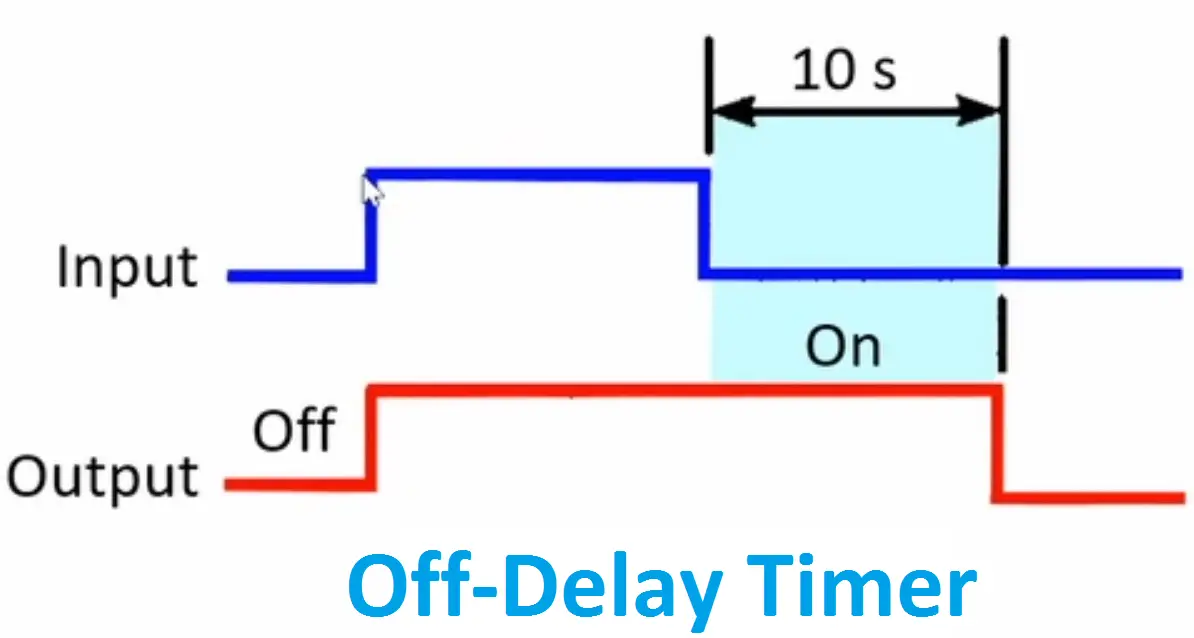
For 5 min, 10 min and 15 min you just have to change the resistor value (r1). Timer functions are most important in plc programming. In monostable operation the output is given by the 555 timer is one shot. The off delay timing diagram can be interpreted in the same manner as the on delay timing diagram. Using timers we can delay the circuit operation.
Simple Delay Timer Circuits Explained Homemade Circuit Projects from homemade-circuits.com When you press the push button of the delay timer then current flows from vcc to gnd now the circuit is off delay timer relay circuit. Say you want a circuit to only be on for 10 seconds and then stop. That will keep a eg. For 5 min, 10 min and 15 min you just have to change the resistor value (r1). Delay timer is a device which is used to take some duration before switch on the main input supply to any equipment. It is called an off delay timer because it works like this Connected appliance with this timer circuit is automatic switch off after some duration of time. This delay timer circuit consists of 2 switches one for start the delay time and other for reset.
Here is a a set of hardware.
Provides complete circuit diagram & source code. All these circuits will produce delay on or delay off … The time delay relay circuit described here is intended for this purpose. The time delay of the circuit can be increase or decrease by using a higher or lower value capacitor as cx. Then this circuit has perfect application. Below are few examples of timer circuits used in different applications. It is called an off delay timer because it works like this This time delay is set by the user. Long delay timer circuit diagram. There is a delay before the output turns off. If you are looking for power supply circuit. The current high output states of 4017b remain high till the power is off. Working of time delay circuit
The time delay relay circuit described here is intended for this purpose. High state at q9 makes moc3041 to conduct. The second standard plc timer is the off delay timer or just tof. The current high output states of 4017b remain high till the power is off. Working of time delay circuit
On Delay Timer Off Delay Timer Working Principle Electrical4u from www.electrical4u.net Normally closed time closed off delay. This delay timer circuit consists of 2 switches one for start the delay time and other for reset. The same relay is turned off when timer reaches/exceeds its set value. This timer was designed mainly to switch off a portable radio after some time: Here is a a set of hardware. You should not choose too much lower value resistor otherwise the discharge rate will be too fast. And second thing is, transistor q1 becomes off, and timing capacitor c1 get disconnected from the below is the circuit diagram for simple delay circuit using 555 ic: The time delay relay circuit described here is intended for this purpose.
It gives power to the as you can see colin feels it necessary to paste the text 78l05 in the circuit diagram which says ldo.
Using timers we can delay the circuit operation. In monostable operation the output is given by the 555 timer is one shot. This is a delay timer using a simple 555 timer. In this way, one can fall asleep on the sand or on a hammock, resting assured that the receiver will switch off automatically. Momentary on switch can be any circuit. High state at q9 makes moc3041 to conduct. On the last diagram we see two. · time delay starts at signal on , switches off on on (no.'s 1, 2, and 3) on the side of the timer as shown. Analyzing the circuit diagram, you can see three buttons. Here is a a set of hardware. Connected appliance with this timer circuit is automatic switch off after some duration of time. The important factor to remember when interpreting the off delay timing diagram is to remember that an off delay timer contains instantaneous contacts. There is a delay before the output turns off.
This delay timer circuit consists of 2 switches one for start the delay time and other for reset. But first you've to turn on the load by pushing the on switch for a moment. For 5 min, 10 min and 15 min you just have to change the resistor value (r1). Analyzing the circuit diagram, you can see three buttons. This timer was designed mainly to switch off a portable radio after some time:
Delay Timer Circuit 6 Steps Instructables from content.instructables.com Power on delay using 555 timer. Using this diagram you can understand on delay and off delay and the explanations are given below. When voltage is removed from the coil, the timer begins timing. Delay on timer circuit working details. That will keep a eg. Posted friday, april 26, 2013. Three types of timers are the most commonly used in the electric circuit. Off course it all depends on what you want to use the circuit for and what delay times are necessary.
This triggers the main triac bt139 and the ac supply for the load becomes available across connector con2.
555 timer dealy circuit is timer circuit which goes off with a delay when voltage between pin6 and pin7 is 2/3rd of the given voltage. The same relay is turned off when timer reaches/exceeds its set value. The current high output states of 4017b remain high till the power is off. … when switch on the circuit then capacitor start charging and amount of. The second standard plc timer is the off delay timer or just tof. Posted friday, april 26, 2013. This is a delay timer using a simple 555 timer. My best way to remember how it works is again by its name. A delay before turn off circuit can be useful for any circuit that needs to be on only for a short period of time, such as a timer. I designed and created this circuit myself it is setup for turning off a fan after 6 minutes when the. On the last diagram we see two. Here is a a set of hardware. Timer functions are most important in plc programming.